Exploring the V3 Burner: Inside the Box and How It Works
Introduction
The V3 Burner is built with serviceability in mind. One of its standout features is how accessible everything is once the box is opened up. If you need a high-level overview of the burner itself, or you want to understand the internal components and the sequence of operation, this unit makes that process straightforward.
At a glance, the V3 Burner is designed so the main compartments are easy to access, the internal layout is easy to follow, and the operating sequence is clear enough to make troubleshooting faster when something is not behaving the way it should.
A Quick Exterior Overview of the V3 Burner
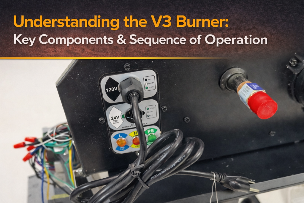
The first thing that stands out on the V3 Burner box is the use of easy-removable thumb screws. These are located on the top and on the sides of the unit, giving quick access to the major compartments without making disassembly a chore.
Once the top thumb screws are removed, the top cover lifts off. Inside, there is a breakdown showing the parts, pieces, and sizes associated with the burner. That is a practical touch, especially when you are identifying components or verifying what belongs where.
Removing the side thumb screws opens up the main burner compartment, where the key operating components are laid out in a way that makes the unit especially easy to service.
Why the V3 Burner Box Is So Serviceable
What makes the V3 Burner especially useful from a maintenance standpoint is accessibility. You can service the unit while it is running and have the important components right in front of you.
That layout matters. Instead of digging through a cramped cabinet or trying to trace wiring and components in a tight space, the burner box presents the operating parts in a way that supports faster inspection and more direct troubleshooting.
When everything is open and visible, it becomes much easier to follow the sequence of operation and pinpoint where a fault may be occurring.
Main Operating Components Inside the V3 Burner
Once the side compartment is opened, the internal logic of the V3 Burner becomes easier to understand. The key components involved in operation include:
- Internal transformer
- Thermostat connection point
- Circuit board
- Pressure switch
- Inducer motor or fan
- Hot surface igniter
- Gas valve
Each of these parts plays a specific role in the startup and heating cycle. Understanding how they work together is the key to understanding how the V3 Burner produces heat safely and reliably.
How the V3 Burner Works Step by Step
1. Power enters the unit
The operating sequence starts when the heater is connected to power. That incoming power is routed first to the internal transformer.
From there, power is sent back to the thermostat connection. That connection then carries power down to the thermostat or control, which is typically located at floor level.
2. The thermostat calls for heat
When the thermostat calls for heat, the signal travels back up to the thermostat connection point on the unit. From there, it is sent to the circuit board, which begins the startup sequence for the V3 Burner.
This is the point where the burner shifts from standby to active operation.
3. The pressure switch is checked first
The first safety check in the sequence is verification of the pressure switch position. The circuit board looks for the pressure switch to be in its normal open position before moving forward.
This check matters because it confirms proper startup conditions. If the pressure switch is not in the expected state, the sequence should not continue.
4. The inducer motor turns on
Once the board confirms the pressure switch is in the correct position, it sends voltage to the inducer motor, or fan.
As that fan starts running, it pressurizes the chamber. That pressure change closes the pressure switch.
So at this stage, the fan is not just moving air. It is also creating the condition needed for the next part of the ignition sequence.
5. The hot surface igniter is energized
With the pressure switch now closed, the circuit board sends power to the hot surface igniter.
The igniter is energized for roughly 30 to 45 seconds. That warm-up period is necessary so the igniter reaches the temperature needed to ignite the incoming gas.
If you are following operation in real time, this delay is a normal part of the sequence and not a sign of a problem.
6. The gas valve opens
After the igniter has had time to heat up, the circuit board sends power to the gas valve. The valve opens, gas flows through, and ignition occurs.
According to the operating sequence described for the V3 Burner, the gas valve remains open for 8 seconds during this initial ignition window.
7. Flame must be proven
After those 8 seconds, the circuit board checks to verify that flame has been sensed.
If flame is successfully proven, the system continues to run. The burner remains on until the heat demand is satisfied and the thermostat ends the call for heat.
If the flame is not proven, or if the burner shuts off before that expected point, that is when troubleshooting needs to begin.
The V3 Burner Sequence of Operation at a Glance
For quick reference, here is the operating sequence of the V3 Burner in order:
- Power enters the unit
- Power goes to the internal transformer
- Power is routed to the thermostat connection
- The thermostat calls for heat
- The signal returns to the circuit board
- The board verifies the pressure switch is normally open
- The inducer motor starts
- The chamber is pressurized
- The pressure switch closes
- The hot surface igniter energizes for 30 to 45 seconds
- The gas valve opens
- Gas ignites
- The board verifies flame
- The heater continues running until the thermostat is satisfied
What to Check If the Burner Shuts Off Too Early
The sequence above also gives you a practical roadmap for troubleshooting. If the V3 Burner does not stay on, the problem is usually found by identifying where the sequence stopped.
For example, if the unit does not move past the early startup phase, you would focus on whether:
- The thermostat is actually sending a call for heat
- The pressure switch is in the proper initial position
- The inducer motor is receiving power and running
- The pressure switch is closing once the chamber is pressurized
- The hot surface igniter is energizing
- The gas valve is opening when it should
- Flame is being sensed after ignition
The basic rule is simple: if the heater turns off before the expected timing in the sequence, it is time to troubleshoot that step specifically.
Why Understanding the Sequence Matters
A burner box can look complicated until the sequence is broken down logically. Once you understand the flow of power and the order of component operation, the V3 Burner becomes much easier to diagnose and maintain.
That is really the value of this design. The unit is not just built to run. It is built to be understood and serviced.
Knowing the sequence of operation helps you answer the most important question in any heating issue: what should be happening right now, and what is not?
Final Thoughts on the V3 Burner
The V3 Burner combines accessible design with a clear and structured operating sequence. The removable thumb screws, open service layout, and visible internal components make it practical to inspect and work on. And once you understand the path from incoming power to proven flame, the whole heater becomes much less mysterious.
If your goal is to understand the unit at both a high level and a functional level, start with the box layout, then follow the sequence one step at a time. That approach gives you the clearest picture of how the V3 Burner operates and where to look when something goes wrong.
Need Help Troubleshooting or Understanding Your Burner System?
Our team at Great Lakes Radiant can help you walk through the sequence of operation, identify potential issues, and make sure your burner system is running safely and efficiently.
Whether you’re diagnosing a shutdown, verifying components, or trying to better understand how your system operates, we’ll help you get it right the first time.
Give us a call, send an email, or fill out our Project Details form—we’re here to help.
📞 (888) 501-0252
📧 sales@glradiant.com
🌐 www.glradiant.com
More Resources
If you’re comparing heater types or want a broader background on radiant heat concepts that these burners interface with, see: infrared vs radiant.
For additional guidance on system behavior and troubleshooting approaches, you can also explore our services page.
To browse related heater options and components, visit products.